Template Manager
The Template Manager enables you to set up the options that will be available when the Project Builder is run.
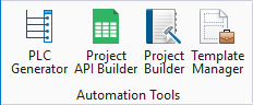
Accessed from:
The following dialog opens:
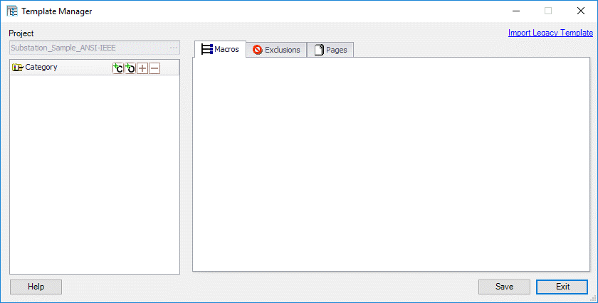
| Setting | Description |
|---|---|
| Project | Select the Browse button and choose a template project in the Browse dialog that appears. Information for the selected project will appear in the Template Manager. Specifically, the categories in the project will be listed on the left side of the dialog. |
| Import Legacy Template | You can import
Project Builder templates from legacy versions of the
Project Builder that were designed to work with versions of
Bentley Substation
prior to 2007. Press the Import Legacy
Template button to display the
Select A Template File To Convert dialog.
Browse to the template.xml file from the legacy version of the Project Builder. Select this file and then select the Open button. If the current project already has a template file, a dialog will appear notifying you that the imported template file will replace it. Select Yes to continue. The software will display a message that the template was successfully converted. You may now edit the imported template information as desired. |
| Category | A category is a major variation of the template project. A complex template may have numerous categories while a simple template might have only one category. Each category has its own set of options. To see the existing options, select the + icon beside the category name. You can also select the Expand All button to display the options for all categories. |
| Create Category | Creates a new category in the Template Manager . A new category field will open in the Category area. Enter a descriptive name for the category in this field and press the <Enter> key. |
| Create Option | Creates a new option within the Template Manager. A blank option name field will appear in the selected Category. Enter a descriptive name for the option and press the <Enter> key. The new option will then be available for editing. |
| Macros Tab | Displays the macros associated with the selected
Option. To add a Macro to an option, select the name of an Option. A blank
macro field will appear at the end of the list of macros included in that
option. (A newly created option will only have the blank macro field.) Click
inside the empty
Macro field to display a Browse button.
Select the
Browse button to display the
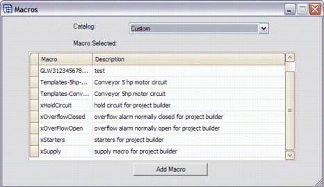
Macros dialog.
Select a Catalog from which to choose a macro. You may have created a catalog specific to this project or it may be your general catalog. Select the desired macro and then select the Add Macro button. Repeat this process for all of the macros needed for the option. You can edit the attributes of symbols and wires in
a macro from within the
Template Manager. The new values are
used with the current option (they are saved with the template and not in the
macro itself). Right-click on the desired macro and select
Edit Macro Text from the menu to display
the
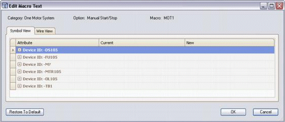
Edit Macro Text dialog.
In either the Symbol View or Wire View tab, you can change the order of the columns by dragging the column heading to the desired position. You can also re-order (sort) the data rows by clicking inside the desired heading. In either tab, you can erase any new values that have been entered and return to the values stored in the macro by clicking the Restore to Default button at the bottom of the dialog. The Symbol View tab lists the symbols that are included in the macro. They are listed by the device ID that each symbol had when the macro was created. If you click the + icon beside a device ID, the attributes of that symbol are displayed. The Current column shows the value of the attribute that is stored in the macro. You can enter a different value in the New column that will be saved with the template and used in this option when a project is generated. Note: If you specify
a new value for
Installation, Location or
Device Tag, it will override the
Maintain Device ID setting in the
Project Builder.
The Wire View tab lists the attributes of any numbered wires within the macro. For any wire attribute, you can enter a new value that will be stored with the template and used with the current option when a project is generated. To enter a new attribute simply click inside the desired field and enter the new value. Within the Macros tab, set the Drawing Set/Page field to select from the pages in the template project on which to place the macro. A page must be selected for the macro to be placed. Use the X and Y fields to enter coordinates for the macro on the page. If no coordinates are entered, 0,0 will be used for placing the macro. |
| Exclusions Tab |
When all of the options are created, you can include additional logic for the options. The Exclusions tab lets you determine what options cannot be combined. Exclusions are a way to eliminate the possibility of selecting two options that cannot exist in the same project at the same time. For example, let's say a conveyor can only be 10 or 20 feet and can either be PLC controlled or manually controlled. A conveyor cannot be BOTH 10 and 20 feet. The heavy-duty oil pump option may be used with any of the other options that use the same type of controls. The user must select all PLC options or all manual options, not both. Select the category the contains the option(s) for
which you wish to set exclusions. Select the option for which you wish to set
exclusions. A blank field will appear in the
Exclusions tab. Click inside this blank
field and a browse button will appear. Select the
Browse button and the
Exclusions dialog will appear.
On the left side of the dialog, select each option that you wish to exclude and then select the right arrow button > to move it to the right side of the dialog (Excluded Options). As you do this, the options you select are removed from the list of Possible Exclusions. If you wish to exclude all the listed options, you can select the double right arrow button >> to select them all in one step. You can use the left arrow buttons < and << to remove items from the Excluded Options list and return them to the Possible Exclusions list. Select the OK button in the Exclusions dialog to enter your selected exclusions. |
| Pages Tab |
You can use the Template Manager to define page deletions based on selected options. This allows the creation of different panel layout sheets to support different enclosures that might be required with different options. The unused pages can be deleted automatically. Select the category the contains the option(s) for
which you wish to set page deletions. Select the option for which you wish to
set page deletions. A blank Pages to
Delete field will appear in the
Pages tab. Click inside this blank
field and a browse button will appear. Select the
Browse button and the
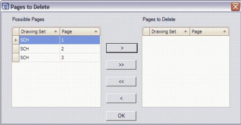
Pages to Delete dialog will appear.
On the left side of the dialog, select each page that you wish to delete and then select the right arrow button > to move it to the right side of the dialog. As you do this, the pages you select are removed from the list of Possible Pages. If you wish to exclude all the listed pages, you can select the double right arrow button >> to select them all in one step. You can use the left arrow buttons < and << to remove items from the Pages to Delete list and return them to the Possible Pages list. Select the OK button in the Pages to Delete dialog to enter your selected page deletions. |